Development of Intelligent Pneumatic Valve Positioner Based on FF Protocol Pang Yanyu Wang Shengcheng姊 School of Information Science and Technology, Beijing University of Chemical Technology Beijing 100029 Communication Implementation The methods and tools for field device development are also explained.
1 Introduction FOUNDATION fieldbus, technology will give revolutionary changes in the field of automation in the 21st century, which has become the industry consensus. Domestic and foreign instruments and control system manufacturers are developing fieldbus products. The product goal of choosing the company's product is very, oh, general, product development self-standard has the following several square toe developers, several dragon machine systems, various viewing devices, this article is intended to be introduced as a fieldbus device. Development of Pneumatic Valve Positioner 2 Development of Fieldbus Device 2.1 Development Method The circuit part of the field bus device includes two communication modules, which are responsible for application processing and bus communication; it is responsible for external measurement and control objects. Each part of the signal output device of the hole function contains the corresponding software and hardware. The direct development method means that the developer develops all the hardware and software of the above two parts according to the 1 discussion and instrument function. After the test and the operability test, the biggest difference is that the shortcomings of the development period are long and the risk is high. The biggest difference lies in the traditional automation of the field bus equipment. The standardization of communication and functions has thus led to the introduction of products that have been implemented by specialized manufacturers that have been certified by scare certification.
That is to say, the above-mentioned Yingxun Leica integrates it with the self-developed Jiji card and other components that complete the measurement control function, so that it can form a fieldbus. This is part of the 01 integrated sweating method for most fieldbus products. Business. It is often called part 01 integrated development method to develop new products. The Foundation's interoperability test, Bega, and the feasibility of this approach, is suitable for manufacturers with limited development capabilities and the desire to quickly introduce fieldbus device products. The advantage of low development costs is that they only have some intellectual property rights. 2.2 Development Steps Summary The above two methods, the development method, and the field device development in line with the Jingjinhui fieldbus protocol can be roughly divided into the following steps: communication part and functional hardware development including development or direct purchase of communication Leica and development equipment function software The opening includes writing a function block transmission block, etc., or purchasing a certified standard function block for the developed device, 0, sending the Foundation registration note 4, giving the device to the Foundation for interoperability and volatility testing, The Foundation recognizes that 12.3 development tools have been developed by many companies, such as Brazil 3131 and the old US companies, providing development tools for plant bus products. With them, users can shorten the development cycle, give play to their technological advantages, and concentrate on development. Various types of field devices with their own characteristics This class uses the company's development tools. The tool mainly includes 1 field instrument round card, FF bus configuration tool monitoring software, ISA bus interface, etc. One of the round card ports adopts 32-bit microprocessor of American Motorola, 1886331; the field bus communication interface chip adopts Japanese wood Shishi Electric's 10 Ding card implementation, the welcome stack soft and functional block software, 1 as the bus link master device 13 or basic equipment. The function block software provides a high-level connection for the development and the blocks required by the device!
3FF bus intelligent pneumatic valve positioner design 3.1 scare bus intelligent pneumatic valve positioner hardware design Intelligent pneumatic valve positioner hardware part adopts double, structure, mainly by communication round card and instrument connected with valve to output field control signal The card consists of a round card using a 1 field instrument round card from the US company. According to the interface signal with the round card and the functional requirements of the intelligent valve positioner, the device card device card structure with the single chip as the core is developed, which mainly includes the valve part feedback part of the port part and the round card connection part. Which keyboard and so on.
0 display circuit selects Hong Kong Jingdian company character type low-power liquid crystal display small module 16 16265, it uses 34 7 1 conversion technology Wen Guan Ming 6 conversion it uses line serial mode and single-chip interface, complete gain setting Signal polarity and refresh rate selection This part contains self-checking and system check to eliminate the gain or offset error of the part or its system. 3.2 The software design of the valve locator device card The task is now connected to the human-machine interface such as 0 display and keyboard menu selection parameters, etc., to achieve self-configuration function, to achieve calculation and correction of various functions, as well as the implementation of basic control algorithms and pulse conversion, etc. The division can be mainly divided into key scan, display button control, data processing, human data processing, watchdog circuit, piezoelectric valve control system setting, and several functional modules such as round card communication, after power-on reset of the microcontroller, system initialization The code does some of the necessary initialization work. The external connection and memory variables are clamped to the known initial state; the initialization interrupt is generated; finally, the flow enters the main program, and the flow 2 initializes the external interface, including the price gate dog channel 25045, the display, and the output driver 1. Initialization interrupt乜拈Set, interrupt, and serial communication interrupts. In the main loop, the mutual conversion between modes is performed by pressing a button. ! 1 is the button counter, according to the different hardware design of the locator, the main features of the locator are low-powered by the characteristics of the ,, the low-voltage performance of the long-time 1 fly 1 gong, the m038-bit processor is used in the 8952 into the 0 converter. 775, its 08 structure guarantees extremely low power consumption values, the program jumps to different modes, performs corresponding actions and control strategies. 3.3FF communication realizes communication between the valve positioner and the FF system network is passed When the communication service is completed, the communication side communicates with the 01 bus 1 bus interface chip and the field bus, and the other side realizes the information exchange through the serial communication and the device card. The latter round card interface we care about provides two serial communication methods for queue serial external connection. Can; 15, with 81. and serial communication with the formula 3. Out of the claws, 10 designs use a dual processor 51 master-slave square 32-bit, Lm, such as. As the core communication card, the 6831 is used as the core of the communication. The card is used as the core valve positioner device card to ensure the communication between the device card and the round card. Call the communication function out 3, 3 pay command 1 send 1 call protocol preamble number 1 line protocol type baud rate bus polarity stop digits, etc. are defined.
If the definition of the baud rate is as follows, the serial communication mode of the timer 1 is selected as follows: This mode is an 8-bit 1 bit format, and the post information is a bit, that is, a 1-bit start bit, an 8-bit data bit, and a 1-bit stop bit porter. When the rate is set to 2400, when the two 8-bit counters of the timer 1 are loaded into the 6-station to start communication, the sender sends a call signal here to 043 to ask if the receiver can Receiving data; after receiving the call signal, if the receiver agrees to receive the data, it will send back the response signal, otherwise it will not receive the data temporarily; the sender can only receive the response signal from the receiver. The data in the data memory unit is sent to the receiver one by one, otherwise the call signal is continuously sent to the receiver to the receiver to receive the receiver to perform the aspect parity check on the received data. If the reception is correct, send back to the sender, the signal, otherwise send back the statement. The sender only sends the task back to the receiver after receiving the return from the receiver. The callback is called Cheng Jin; otherwise, the call is resumed and the data is resent.
The serial communication processing program of the device card side uses a serial interrupt. When the serial port receives the signal, it enters the receive interrupt. If the call is a valid call during the interrupt, the receive flag is set, otherwise it returns. The main program judges the reception flag bit, enters the reception transmission subroutine, or executes sequentially. The circle is the calling party, and the dual-card communication is mainly initiated by the call sending and receiving data. The serial communication function provided by the function block shell completes the interruption. D 4 Conclusion The protocol-based intelligent pneumatic valve positioner developed has been realized. The communication and function block application with other fieldbus devices proves that the feasibility and practicality of the design scheme will be carried out for specific productization and certification testing.
3 Yang Xianhui. Fieldbus technology and its applications. , published by Tsinghua University, Beijing
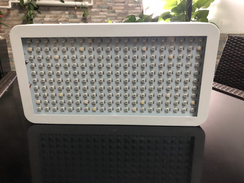
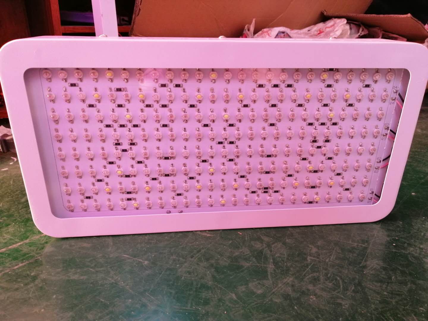
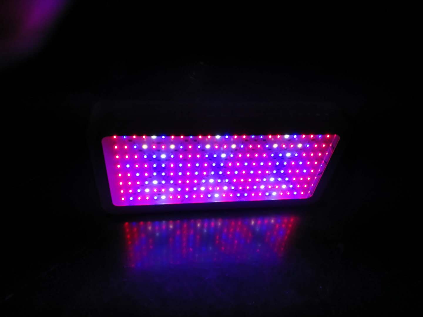
LED Grow Lights 2000W, with 200pcs double chips led, 3pcs fast-speed cooling fans, we have double switch grow light/red+blue lighting/3500k white lighting, High power System Led Grow Light works very well for plant growth.2000W Grow Lights For Indoor Plants.
OEM:
Customzied box MOQ 500pcs.
Customzied logo MOQ 100pcs
2000W product photo:


Led Plant Lights,Cheap Grow Lights,Led Plant Grow Light,Led Grow Lamp
Shenzhen Wenyi Lighting Technology Co., Ltd , https://www.szwygrow.com