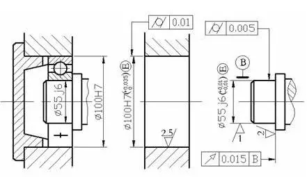
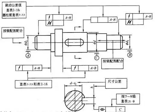
How to choose parameters such as dimensional tolerance, geometric tolerance and surface roughness in mechanical design?
In general, first determine the dimensional tolerances and then determine the geometric tolerances. Reasonable tolerances are first of all functional requirements, followed by the processability of the process, and finally the processability of assembly and maintenance.

For example, in terms of cooperation, it is all about the hole shaft fit. This is not necessarily a round hole and a shaft. It can be square, but why is it usually round and easy to machine. Traditional processing methods such as turning, milling, drilling, and grinding are mostly circular processing methods. Now with the popularity of laser cutting and wire cutting (low cost), the application of shaped holes is also more.
Since the traditional method of machining is a circular process, the choice of the hole shaft fit will have a choice of base hole or base shaft. Usually, the processing of our holes is directly formed by drilling, reaming and milling. In this way, for the convenience of processing, we should choose the size of ready-made tools (bit, reamer, milling cutter) for the size selection. For example, the tool with diameter 14 is rare, so it is convenient to choose 12 or 15, 16 The specifications of the purchase, so the processing cost is very low, such as the choice of diameter 30 is not selected 27, although you need 27 for calculation is enough.

In terms of tolerances, the holes are machined (whether the holes on the plate or the holes on the pipe), and the tolerance zone is as wide as possible (positive) tolerance, because the tool with special tolerance is very expensive and difficult to buy, when the tool rotates during machining. Jitter (one of the accuracy of the device) results in a size that is slightly larger than the tool diameter. At this time, the machining of the shaft is usually processed by the car, and is not limited by the precision of the tool. Therefore, the base hole system is a low cost option (that is, the processability is good).
At this time, if the shaft you design is the motor output shaft, it can only be made with the base shaft, or it can be matched with the outer ring of the bearing.
How to choose the matching, that is to say, when the clearance, transition, and interference fit are used. Simply put, this is not important, does not affect the accuracy of the assembly (if there is a screw connection), you can choose the clearance fit, the direction of rotation is one-way, and it is a continuous working state, that is, clearance fit. As for the choice of the gap size, it is difficult to see the assembly, and the looser the easier it is to assemble.
For example, if the one-way intermittent operation and the rotational displacement require a low-precision, low-speed, hole-type hole with a flat key, the clearance fit can also be selected, but two 90-degree spaced-apart set screws are required. Tight positioning. If there is a key fit, one of the set screws should be locked above the flat key.
Similarly, in terms of rotation, if it is a one-way intermittent rotation, or a forward and reverse movement, select the transition fit. At this time, it is also necessary to have a set screw. If it is a large torque, then the interference fit is generally selected. This usually requires a press fit or even a hot suit.
Geometric tolerance is a supplement to dimensional tolerances, so the choice of tolerance zone should be less than the dimensional tolerance, otherwise it makes no sense.
For geometric tolerances, it is important to understand the meaning of geometric tolerances. At this point you can make the right choices and the content and scale to be controlled.
For example, if the tolerance of a workpiece is 0.2mm, then if the plane on both sides of the width requires a parallelism, it needs to be less than 0.2mm, otherwise it will lose its meaning. In many cases, the tolerance of this width is not high, but The parallelism is very high, it may be 0.05mm, then this parallelism is very important, usually it has a significant impact on the assembly.
Having said that, I don’t know if the expression is clear, let’s explore and learn from each other.

Let’s talk about roughness
This thing is more hanging, I also know it for a long time. Generally, the general machining process basically reaches 12.5. For machining, this is relatively rough. This kind of requirement can be used if the appearance requirements are not high. I suggest that the unprocessed requirements of ordinary machining parts can be used, such as sheet metal. Piece shears, etc., personally think that there is nothing (tolerance) required to use this value, if better 6.3, these cars, milling, can be easily achieved, 3.2, 1.6, or less roughness Need to grind, which means the cost rises, so if there is no higher requirement, it is better within 3.2, the tolerance band of 3.2 needs 0.01 precision level, and 0.05 of 6.3 is also acceptable.The question is, why is it so light, which involves the size of the effective contact surface and is directly related to fastening, wear and stress. The surface of the bearing roller that I have processed here requires super-finishing, which is actually a polishing process, in order to obtain a better and more uniform force. The mechanical seal also requires high roughness requirements.
(Source: Machine Tool World)
Active Luminous Sign,Solar Custom Guidance Sign,Custom Active Luminous Signs,Led Active Luminous Traffic Sign
Jiangsu chuanglv Transportation Facilities Co., Ltd , https://www.clsolarlights.com