2.3 Burning surface change and feature quantity calculation
Use the program to modify some dimensions of the graph at regular intervals (such as the inner diameter of the cylindrical geometry). Because Pro/ENGINEER has parametric properties, the size can drive the change of the graph, so you can simulate the whole dynamics of the charge. The combustion process, at each moment, using the functions provided by Pro/Toolkit to accurately calculate the charge parameters such as the combustion area. However, the specific implementation of the program also needs to address the following major issues.
2.3.1 Distinction between burning surface and non-combustible surface in charging
The Pro/Toolkit itself has a function to accurately calculate the surface area, either to calculate the area of ​​the entire graph or to calculate the area of ​​a surface. However, Pro/ENGINEER does not automatically distinguish between burning and non-combustible surfaces. Careful study of the Pro/ENGINEER modeling method is not difficult to see, in the charge modeling, all non-combustible surfaces are produced by adding materials, and the burning surface is almost always through non-added materials, such as punching , cutting materials and other methods are generated. Therefore, by accumulating the surface area of ​​each non-added material type by program, the burning area can be accurately calculated. Considering that the number of the surface of the burning surface is generally larger than the number of the non-combustible surface, the total area and the area of ​​the non-combustible surface are calculated in the program, and then the difference between the two is used to determine the area of ​​the burning surface.
2.3.2 Implementation of the principle of parallel shift
The charge is burned according to the parallel transition law. Therefore, the change of the size during the simulation of the combustion process must conform to the principle of parallel shift. For simple geometric features such as cylindrical surface, only the radius or diameter can be changed, but it must be special for the slope. deal with.
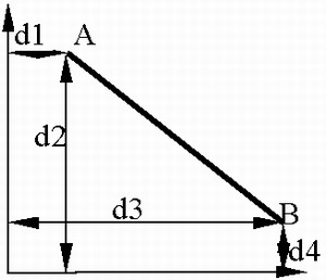
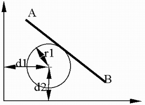
The size of the bevel positioning is generally shown in Fig. 5 in Pro/ENGINEER. In the case where the amount of flesh thickness is constant, any of the redesigned dimensions d1, d2, d3, and d4 cannot satisfy the parallel transition, and the construction line solves this problem. The problem provides an easy way. The construction line only plays a role in the Pro/ENGINEER drawing process and does not add new features to the drawing. As shown in Fig. 6, the construction line can be used as a circle tangent to the slope. To achieve parallel displacement, it is only necessary to change the radius of the circle. In fact, most intersecting faces in the charge pattern have chamfers at the intersection, and changing the chamfer radius allows chamfering and parallel displacement of the tangent plane.

Figure 5 General positioning of the slope under Pro/ENGINEER

Figure 6 Modified bevel positioning
Previous page next page
Tool Set,Craftsman Tool Set,Mechanic Tool Set,Socket Wrench Set
SHANGQIU DING LIAN INTERNATIONAL TRADE CO. ,LTD , https://www.dingqitools.com