1 Introduction
EDM (Electrical Discharge Machining (EDM)) has become one of the main directions of science and technology workers because of its unique advantages and its important role in mold manufacturing, making its process control optimization and processing equipment intelligent.
The concept of intelligent control first appeared in the 1960s. The intelligent control system has self-learning and self-adaptive capabilities, and can independently adjust its own control structure, parameter methods, decision-making planning or generalized problem solving to complete the task. The intelligent control of the process currently includes three aspects: (1) expert control; (2) fuzzy control; and (3) neural network control.
Intelligent control is essentially a predictive control—predictive model, rolling optimization, and feedback correction. It frees the EDM control from the strict mathematical model constraints, treats the process as a "black box", completely dissects the internal description of the system, and uses the membership function to characterize and describe the qualitative information to simulate the thinking mode of the skilled operator. According to the current processing state and the previous decision to adjust the parameters, thereby achieving the purpose of improving the processing efficiency and stabilizing the processing. Therefore, the primary solution to the premise problem is what the input parameters and output parameters of the "black box" are, and what parameters need to be detected and controlled, which must be determined in conjunction with the special process rules of EDM.
Further research has shown that spindle servo feed, motor lift (lift), and discharge gap adjustment are the main control quantities of EDM. In fact, EDM excitation has not been satisfactorily explained so far. The detection of EDM discharge gap state is an unavoidable difficulty in EDM intelligent control. Therefore, it is necessary to apply new advanced technologies to obtain accurate discharge gap conditions, and provide pre-technical support for research and implementation of intelligent control of EDM processes.
2 Control of EDM process and identification of gap discharge state
It is well known that in spark discharge machining, the discharge must be a short pulse discharge. The duration is generally 10-6 to 10-3 s. If the discharge time is equal to or greater than 10-2 s, it is converted into an arc discharge, so that the processing cannot be performed normally. Therefore, many complex variables must be detected and controlled in real time on the microsecond or millisecond level.
The objectives of EDM process control are: (1) to ensure that the arc is damaged to avoid damage to the workpiece, and to maintain a stable processing state; (2) to meet various specifications such as surface roughness and precision; (3) to meet high-speed machining as much as possible Requirements. So the first problem encountered was to have a highly sensitive EDM automatic control unit.
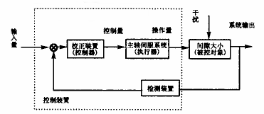
Compared with other traditional processing methods, the EDM process is a slow process, so its control objective function is to ensure the surface quality and processing accuracy, with the shortest processing time (the fastest processing speed). achieve. The block diagram of the EDM control system is shown in Figure 1.

Figure 1 Block diagram of the EDM control system
To achieve EDM, it is necessary to maintain a reasonable distance between the tool electrode and the workpiece. Within this distance range, the pulse voltage can be continuously broken through the medium to generate spark discharge, and the medium can be de-ionized after the spark channel is extinguished. The effect of the ion ion) and the discharge of the product. This distance is called "machining gap" or "discharge gap". Whether the gap is reasonable is limited by factors such as pulse voltage, energy of the spark channel, and dielectric constant of the medium. In general, the discharge gap of EDM is in the range of several micrometers to several hundred micrometers. And within a certain time range, the pulse discharge is concentrated in one area; in another period, it should be transferred to another area. Only in this way can carbon deposits be avoided and arcing and localized burns can be avoided. Therefore, the discharge gap is the main object of control. At present, gap voltage is used as a sensing signal reflecting the gap size on many machine tools. When the gap is too large, the U value is small due to short circuit and short breakdown delay. In any case, as the gap voltage increases, the discharge gap also increases. Thus, the size of the discharge gap that cannot be continuously measured during processing can be obtained by continuously measuring the processing gap voltage. However, the interaction between the gap voltage and other control parameters is large. Therefore, accurate detection of the state of the spark discharge gap has become an unavoidable problem.
There are five basic forms for studying the "temporal state" of a single pulse waveform in an EDM process, namely normal spark discharge, transitional arc (recoverable unstable arc), stable arc, short circuit, and open circuit (no load). Their characteristics are:
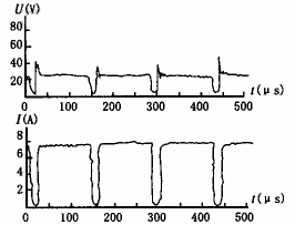
(1) Normal spark discharge: High-frequency clutter components appear on the discharge voltage waveform during discharge, and the peak value is large, and there is a breakdown delay phenomenon. In the process of forming a spark discharge, the voltage and current waveforms are straight and regular. See Figure 2.

Figure 2 Normal spark discharge voltage and current waveform
(2) Transition arc: On the discharge voltage waveform during discharge, there is almost no high-frequency clutter component, the breakdown delay is not obvious, and the waveform is irregular. This waveform can be restored to normal spark discharge by servo control, or it can be restored to normal spark discharge by the change of gap state. Therefore, it is proposed as a theoretical study, and no special measurement is required in the actual machining control process (this state is not considered in this paper).
(3) Stable arc (non-recoverable burnable stable arc): In the case of poor gap discharge conditions, such as deep hole machining, the stable arc is formed to burn the workpiece, and the tool electrode and the workpiece surface will form a local convex or concave surface. The pits, voltage and current waveforms are very smooth. After the arc is formed, if the black spots are not erased, the process cannot be restored to normal. See Figure 3.

Figure 3 Stable arc discharge voltage and current waveforms
(4) Short circuit: The voltage is very low and the current waveform is smooth. Although the short circuit itself does not erode the workpiece and does not damage the electrode, it creates a hot spot in the short circuit, and it is easy to cause arcing when the short circuit is eliminated.
(5) Open circuit: The gap processing medium is not broken down.
In order to clearly describe the state of the discharge gap, the gap state diagram given herein is processed. In the actual EDM process, these five types may appear, even in a single pulse unit. The situation of short circuit and open circuit is very different, and will not be described in detail in this article. The voltage and current amplitude characteristics of the two states of normal spark discharge and stable arc discharge are relatively close. It is difficult to distinguish only the magnitudes of voltage and current because their gap voltage and current amplitude difference are small, and As the process standards change, it also fluctuates within a certain range.
There are two main types of detection techniques since the 1970s: high frequency detection and breakdown delay. Due to the introduction of optoelectronic technology, we have adopted a new method - setting the threshold voltage method. Starting from detecting the discharge gap voltage, the optocoupler is used to shield the interference, and the acquisition information is connected to the PC for processing.
3 Electric spark discharge gap state detection method and working principle
3.1 High frequency detection method
The high frequency detection method distinguishes spark discharge from arc discharge by detecting high frequency components on the gap voltage. In the spark discharge, the gap voltage has a strong and stable high-frequency component (frequency from several megahertz to several tens of megahertz); and in the arc discharge, the high-frequency component of the gap voltage is weak or even absent. Therefore, the high-frequency signal on the gap voltage can be extracted, amplified, and compared as a basis for distinguishing between spark discharge and arc discharge. This method not only distinguishes between spark discharge and arc discharge, but also further distinguishes arc discharge into stable arc discharge or transition arc discharge, but it is difficult to judge the discharge state of a single pulse, and the circuit is complicated and the stability is poor.
3.2 Breakdown delay method
The breakdown delay method is designed according to the fact that there is a certain breakdown delay time when the spark is discharged, and there is generally no breakdown delay time when the arc is discharged. Although it can not distinguish between transitional arc discharge and stable arc discharge, and can not effectively distinguish the discharge state transition occurring in a single pulse, it has the advantage of discriminating the discharge state of a single pulse, and the detection circuit is a digital circuit, anti-interference The performance and stability are very good, and it is also convenient to connect with the computer control system on the EDM machine.
3.3 Setting the threshold voltage method
It can be seen from the identification of the front discharge gap state that a single pulse of normal spark discharge and stable arc discharge is measured by a very sophisticated instrument in the laboratory. In the practical application, various interferences occur, and the voltage and current characteristics of the normal spark discharge and the stable arc discharge are similar and difficult to distinguish. Moreover, even if it is detected, there is no standard for the computer to recognize. This problem can be solved by setting the threshold voltage method.
Set a reference voltage between the arc discharge and the spark discharge. The voltage values ​​of the spark discharge and the arc discharge are detected by an amplifier linear method, and they are proportional to each other by using a photocoupler. At normal discharge voltages, the photocoupler (GD) is essentially off and is substantially saturated during arc discharge. Set the reference level Uref1 as shown in Figure 4. The threshold voltage method is named. Due to the function of the optocoupler, not only the discrimination of the normal spark discharge and the stable arc discharge becomes simple, the circuit is simplified, the circuit interference can be greatly suppressed, and the machine power system is completely isolated from the digital system.
Next page
Phlizon is a new high-tech enterprise, specializing in research, production, sales services of LED Grow Light.The headquarters is located in Huilongda Industrial Park, Shilongzai ,Shiyan Street, Baoan District, Shenzhen, China.So far we have overseas warehouses in the United States, Germany, the United Kingdom, and Spain.we strive to provide convenient and highly efficient solution services.
Adopts Samsung LED 5630 as light sources, which has the advantages of high performance, low energy consumption and stability.
Input voltage:AC100-240V,easy to use, safe and suitable for any country.
LED Lifespan is reach up to 50,000 hours.
Suitable for all kinds of plant growth, flowering and yield
Safe and environmental protection, free from pollution and harmful substances

Features:
High power brand Samsung 5630 led with high par vaule100-277v/200-480v for industrial planting
Higher PPFD value per unit area
Full Spectrum Grow Light mimics natural sunlight for different period of growth
Passive heat sink and die casting aluminum shell
Aluminum body for a good heat-dissipation
Elegant appearance
Easy to install by minute
More convenient and simple for maintenance
Energy saving,environmental friendly
3-5 Year warranty
Applications
Hydroponics,Horticulture,Agriculture and Greenhouse
Locations:Farm,Exhibition,Garden,Home,Urban,Bonsai,and University Lab
Growth of Fruits,Vegetables,Flowers and so on
Seeding,Rooting,Breeding,Flowering and Fruiting period

Phlizon is the manufacturer factory and we sell our products at a low price directly, besides all our Power supply, Fans and wire all are Fire-resistant material,won't catch fire.
We currently have warehouses in the UK, USA, Canada,Spain, and Australia,and we are working on opening more warehouses in other countries to shorten our delivery time.
We have strong OEM/ODM capabilities, with experienced teams, full post-sales support and an established quality control system.
We promise to provide high-quality products with competitive prices, fast delivery, and responsive services for our clients.
Cautions
1.This light is not waterproof, do not spray water
2.Never touch and hit the Light while it is working.
3.Lighting work environment is -20 ~ 40 °C, 45% ~ 95% RH.
4. Please cut off the power when there is a lightning strike.
5. Make sure that the mounting position can withstand 10 times the weight of the light.

Quantum Board Grow Light,Quantum Board Grow Light Kits,Led Quantum Board Grow Light,200W Quantum Board Grow Light
Shenzhen Phlizon Technology Co.,Ltd. , https://www.szledaquariumlight.com