[ Huaqiang Security Network News ] 

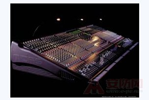
The introduction of mixer tuning techniques is the focus of this article in the China Security Network Xiaobian. First of all, we know that mixers are widely used in broadcasting, theaters, dance halls, gymnasiums and other places. Common mixers have 8 channels, 12 channels, 16 channels, 24 channels, etc. Each channel can process signals separately, such as signal amplification, tone adjustment, spatial positioning of sound, and mixing. The mixer can be divided into three parts: input, bus, and output. Mixer input section: socket and function key arrangement.

Mixer tuning skills introduction
(1) is a microphone (MIC) input socket.
(2) is the line end. It is a large three-pin socket, generally used for input holes of other sound sources except the microphone.
(3) is an insertion socket (INS). It is normally in the on state. When the big three-pin plug is inserted, the signal input by (1)(2) is taken out from the core of the plug, and after being processed by the external device, it is returned to the mixer from the other core, so it is also called Going out again and into the socket.
(4) is the fixed value attenuation (PAD). When you press this button, the input signal will be attenuated by 20dB (ie 10 times), and some will be 30dB.
(5) is Gain, which is the volume preset knob.
(6) is a low cut button (100 Hz). When this button is pressed, the components below 100 Hz in the signal are cut off.
(7) is equalization adjustment (EQ). HF high frequency, MF is the intermediate frequency, and LF is the low frequency.
(8) is the auxiliary knob (AUX1; AUX2; AUX3; AUX4). Adjust the level of the signal sent to the corresponding bus. The signals of AUX1 and AUX2 are taken out from the pre-fader and are not affected by the fader. AUX3 and AUX4 are controlled by the fader.
(9) is a sound image adjustment (PAN). Adjusting the distribution of the sound source in space, if adjusted to the left, is equivalent to placing the sound source on the left (left channel). Use this button when you want a stereo location.
(10) Attenuator (Fader). That is, the fader adjusts the volume of the road.
(11) Monitor button (PFL or CUE). Press it and plug it into the headphone jack of the mixer to monitor the signal.
(12) Turn on the button (ON). Press it and the signal is connected to the mixer for mixing.
(13) LR button. Press it and the signal is sent to the left and right busbars via the fader and PAN.
(14) 1-2 button. Press it and the signal is sent to the group bus 1 and 2 via the fader and PAN.
(15) 3-4 buttons. Press it and the signal is sent to the group bus 3 and 4 via the fader and PAN.
It is worth noting that some consoles do not have buttons 13, 14, or 15. Bus (BUS) is the input channel of each channel
The confluence of the signal is then passed to the output section. There are generally four busbars, the left (L) right (R) output bus, the monitor bus and the effect bus. As for the output part of the mixer, it is relatively simple and will not be described here.
Here are some details about the operation:
First, connect all systems before booting. Adjust the fader, equalizer (EQ), PAN PAD GAL, etc. back to the starting state
Second, after booting
(1) First turn the volume of the source device (such as CD) to the maximum undistorted state.
(2) Adjust the mixer's sub-fader of the input channel at 70%, and increase the input gain (GAIN) knob to the PEAK indicator until it is not lit.
(3) Adjust the volume to output the main fader, so that the output VU meter pointer swings around 0VU, and the long-term pointer is not allowed to exceed +3VU. At this time, the main fader position should also be in the position of 50%~70%. The input gain or source output level can be adjusted accordingly.
(4) If you still feel that the loudness of the speaker is not enough, you can turn on the power amplifier volume knob. Note that the power amplifier must not enter the clipping state, otherwise it should be replaced with a larger power amplifier.
Previous123Next page

Say two sentences
Disclaimer: All works that indicate the source of this website are copyrighted or entitled to use by this website. Welcome to reprint and indicate the source. Non-this works are all from the Internet, and the purpose of reprinting is to transmit more information. It does not mean that this website agrees with its views and is responsible for its authenticity.
(function() { var s = "_" + Math.random().toString(36).slice(2); document.write(' '); (window.slotbydup=window.slotbydup || []).push({ id: '3447380', container: s, size: '400,60', display: 'inlay-fix' }); }) ();
(function() { var s = "_" + Math.random().toString(36).slice(2); document.write(' '); (window.slotbydup=window.slotbydup || []).push({ id: '3447380', container: s, size: '400,60', display: 'inlay-fix' }); }) ();
(function(){document.write(unescape('%3Cdiv id="bdcsFrameTitleBox"%3E%3C/div%3E'));var bdcs = document.createElement("script");bdcs.type = "text/ Javascript";bdcs.async = true;bdcs.src = "http://znsv.baidu.com/customer_search/api/rs?sid=15536151422878601506" + "&plate_url=" + encodeURIComponent(window.location.href) + " &t=" + Math.ceil(new Date()/3600000) + "&type=3";var s = document.getElementsByTagName("script")[0];s.parentNode.insertBefore(bdcs, s);}) (); Window.changyan.api.config({ appid: 'cysS0iXyl', conf: 'prod_87f6facbc974deee91a037fe4bfa0ec1' });
Smart Light,Smart Lamp,Rgb Light Bulb,Smart Led Lights
Guangdong Smart Street Lighting Co., Ltd , https://www.fldlight.com