Abstract: In order to solve the problem of dimensional and shape tolerance of aluminum alloy thin-walled parts in mechanical machining due to deformation, high-speed, low-feeding and low-cutting processing methods are used to complete all related dimensions of parts by one clamping. Processing, thereby reducing the deformation caused by excessive cutting force during the machining process, avoiding the error caused by the inconsistency between the machining reference and the design basis, and improving the dimensional accuracy and shape accuracy of the part.
1. Proposal of the problem
During the machining of parts, deformation is often caused by internal stresses, especially the processing of colored light metals such as aluminum and magnesium alloys. Deformation in the form of warpage, side bends and twists caused by internal stress frequently occurs, which will seriously affect the processing quality and processing efficiency of the parts, especially for thin-walled and thin-plate parts. How to minimize or eliminate the deformation of parts and ensure product quality and production efficiency has been the subject of our research for many years.
2. Cause analysis
In order to improve the processing and use properties of aluminum alloys, it is necessary to increase the strength by heat treatment (quenching treatment + aging treatment) before processing. The material generates a large internal stress during the quenching process. The aging process cannot completely release the internal stress generated during the quenching process. In the subsequent machining process, new cutting stress is generated. As the material is continuously removed, the internal stress is balanced. The state is broken and the internal stress is redistributed until the new balancing process is reached and the deformation occurs, so that the part loses the processing precision it should have. Also, when the stress on the surface of the part exceeds the strength limit of the material, cracks are generated.
3. Solution
For the above reasons, the aluminum alloy thin-walled and thin-plate parts are processed by the “sleeve material†method. The “sleeve†method is a processing method in which all the dimensions are processed in one setup and then the parts are removed from the blank. The casing process includes milling top → rough milling cavity → rough milling shape → fine milling shape → finishing milling cavity → finishing milling bottom → point (drilling) hole → cutting and other processes. Since the whole process is completed in one setup, before the cutting, since the part is connected to the bottom surface of the blank material, the internal stress is generated without causing large deformation of the part, and the part size is stable throughout the process. When cutting, it is necessary to make the blank material and the part material have a 0.1mm adhesion on the bottom surface to ensure that the part has sufficient strength throughout the "sleeve" process to resist the cutting stress generated during the machining process.
After the part is cut from the blank, the part is deformed due to the stress release, but the relative dimensions of the part will not change, and only the correction process is required to level all the dimensions and shapes of the bottom surface.
4. Application examples
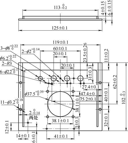
As shown in Figure 1, the aluminum alloy sheet parts are processed by the “sleeve material†method as follows:
(1) Process development: Since the final thickness of the part is 2mm, stress is easily generated during the processing of the blanking machine, and deformation occurs. According to its structural characteristics, the specific processing flow is blanking → aging → milling benchmark → grinding benchmark → deburring → Milling shape ("case" method processing) → deburring → calibration → inspection → storage. The stress generated during the blanking process is eliminated by the aging process; the milling reference and the grinding reference process ensure that the reference plane is in full contact with the positioning surface of the fixture, and the positioning is accurate and reliable, thereby ensuring all dimensions in the thickness direction in the milling profile process. Since the two processes belong to the light processing, the slight stress generated in the process causes the deformation of the part to not affect the processing size; the milling shape ("case" processing) completes all the dimensions of the part; through the deburring process Remove all kinds of burrs and flashes generated during processing to ensure accurate positioning of subsequent processing; correct the deformation caused by parts after machining with large margin through the calibration process; verify the conformity of all dimensions and pattern requirements of the inspection process; submit.

figure 1
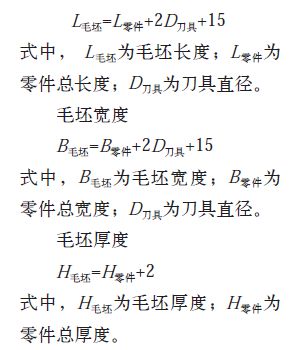
(2) Blank size determination: blank length

In the formula, the H blank is the thickness of the blank; the H part is the total thickness of the part.
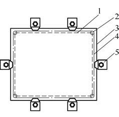
(3) Fixing method: Due to the small size of the parts, a combination fixture is used to position the bottom surface and press the edge of the part (see Figure 2). The pressure plate must be evenly distributed around the periphery of the blank to ensure that the bottom surface of the part fits snugly against the clamp during the entire machining process. The pinch position must be outside the tool path boundary to avoid milling the platen during machining.

figure 2
1. part contour 2. tool 3. blank boundary
4. Knife boundary 5. Platen
(4) Implementation of the “kit material†process:
1 tool selection. In order to reduce the amount of deformation of the part in the process of the casing, under the premise of ensuring the processing efficiency, try to use a tool with a small diameter. The smaller the tool, the smaller the cutting force during machining and the lower the stress generated. This part is machined with φ 6mm end mill. 2 Determination of the amount of cutting. In order to reduce the cutting force, the cutting amount is selected according to the principle of high speed, high feed and small depth of cut. According to the rigidity and the highest working speed of the machine tool at the processing site, the speed is selected as S=4 000r/min, the feed speed is F=1 000mm/min, the radial depth of cut is 50%D, and the axial depth is 0.2mm.
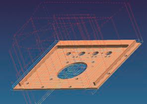
3 preparation of the program. The milling shape is carried out on the milling center. After the digital model is built according to the part pattern by the programming software, the NC program is programmed according to the “set material†method including the tool path sequence in the process. During the programming process, the tool and cutting amount are selected according to the above (see Figure 3). ).

image 3
(5) Implementation effect: Through the actual processing verification, all the dimensions of the corrected parts meet the requirements of the drawings. The actual machining time of the milling profile process is 33min, which meets the batch production requirements.
5 Conclusion
The “sleeve material†method has been widely used in the batch production and processing of aluminum alloy structural parts in our factory. It not only improves the processing efficiency and product quality, but also eliminates the error caused by the mismatch of design basis and process reference, avoids the error caused by the non-coincidence of design basis and process reference, avoids the compression tolerance due to dimensional chain conversion, and simplifies the process specification process. And the processing of the parts.
This article was published in the metal processing (cold processing), the fourth issue of 2015, please indicate the source.
Pvc Double Doors,Interior Double Doors,Wood Entry Doors,Wooden Doors For Home
Foshan QI'AN Fireproof Shutter Doors Co., Ltd , https://www.fsqianfiredoor.com